Rhymney Railway - Brake Van №29
This page has been created to document the building of a 4mm scale model of one of the old brake vans with two open verandas. It has been prompted by the HMRS making available a scan from their Metro-Cammell drawings collection (HMRS drawing reference 19843) and the knowledge that Jonathan David was preparing a version of this drawing to be published in the Archive of the Welsh Railways Research Circle, an excellent follow-on to his article in the HMRS Journal on RR goods wagons (Volume 22, Number 10, April – June 2017, p. 331-345) and his talk to the Circle.
So, on to the model. The first job was to collect all the photos I could find of this type of van: I know of one at Bargoed (number illegible), several in the Real Photographs collection taken probably at Cardiff Docks (numbers 18, 26, 28 & 30) and one (34) involved in a collision with an ADR loco (Welsh Railways Archive Vol. II No. 10 p.236). Although very similar, there are detail differences between the vans, particularly in planking, buffers and brake gear. There are clearly going to be some modelling challenges but at least the vans were simple in two respects: they appear not to have had safety hangers for the brake push rods, nor sanding gear. I really wonder how effective they would have been in holding back a loaded coal train going down the valley on a typically wet day.
The first consideration is that one can see the inside of the verandas. This had a 4×4″ frame with 1″ planks rebated into the framing. I consider it too difficult to adopt this approach as cutting the rebate would not be easy and scoring very thin plasticard would almost certainly cause distortion. Normally I'd use 30thou plastic or 0.8mm ply (unpainted bits) for wagon bodies but this would be visibly too thick. Hence I've decided to go for a compromise and make the bodywork of 20thou. A consequences will be the need to fill the joint between side and ends to simulate single corner pillar, laminataion to get framing thickness correct, reinforcement of van body to stop distortion, lamination of headstocks and solebars for strength. The van floor was 2″ thick but the only ply I have is either nominally 0.5 or 0.8mm thick so I have decided to use the 0.8mm and reduce the height of the main body ends to keep the overall height correct.
With 5′11½″ between the ¾″ thick W irons and padding between the W irons and solebars, the distance between solebars was 6′2″corresponding to 24.7mm: the Masokits W irons that I intend to use measured as 25.2mm hence one can't have scale thickness solebars without some drastic alterations: at least at the W irons the maximum possible is 1.75 instead of the scale figure of 2mm. With 20thou sides/ends laminating with 60thou Slaters microstip will be just a bit too thick so I decided to use this and file down to acceptable thickness by the W irons.
So stage one of actual modelling, mark out:
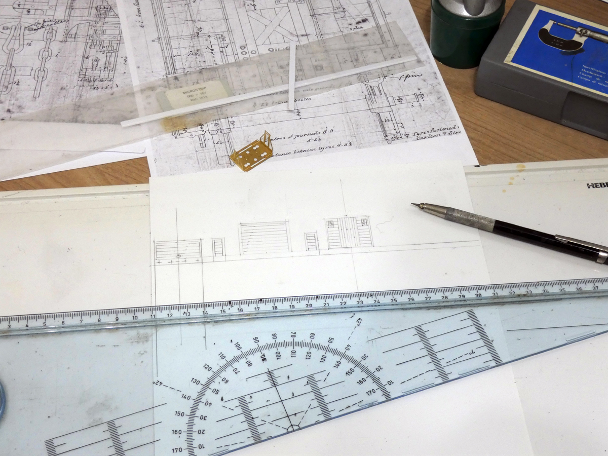
- sides including solebars, full length and accurate heights
- ends including headstocks full width minus twice side thickness (roof radius not shown on drawing, but estimated at 10′)
- floor full length minus twice end thickness, width full less rebates for sides
- headstock lamination from 60thou and width minus 2 side thickness
- solebar laminations from 60thou less twice thickness of end plus headstock lamination
While waiting for delivery of some plastic strip I've started work on scribing the planking. My first trial was to grind the blade of a scrawker to be flat on one side and with a shallower finish to the other so as to simulate the type of boarding used: the cutter however did not perform well, having a tendency to wander away from a straight edge. I therefore used a conventional blade and held it at approximately 45° so the edge next to the rule was vertical: without moving the rule I took a scalpel and used it to scrape the other edge of the groove to make it shallower and wider. Whether or not this works won't really be clear until after the van is painted.
The next step was to consider the half round beading that covered the edges of the planking and framing. I couldn't find any half round materail of the appropriate size so there appeared to be two options, cut a groove and add round rod or thin some rod and stick it where the joints would be. I chose the latter, thinning the 0.5mm plastic rod by scraping with a scalpel.
Washer plates and door hinges are being made from 5 thou plastic sheet with bolt heads cut from tiny bits of 10thou strip. These look much too big, and the wrong shape, to represent bolt heads but are OK for representing nuts: I hope they will look acceptable once painting and weathering is done. I must try to find a better alternative for the future. The window frames are represented by 5thou strip in the openings: I don't intend to model the part of the frame inside the body.
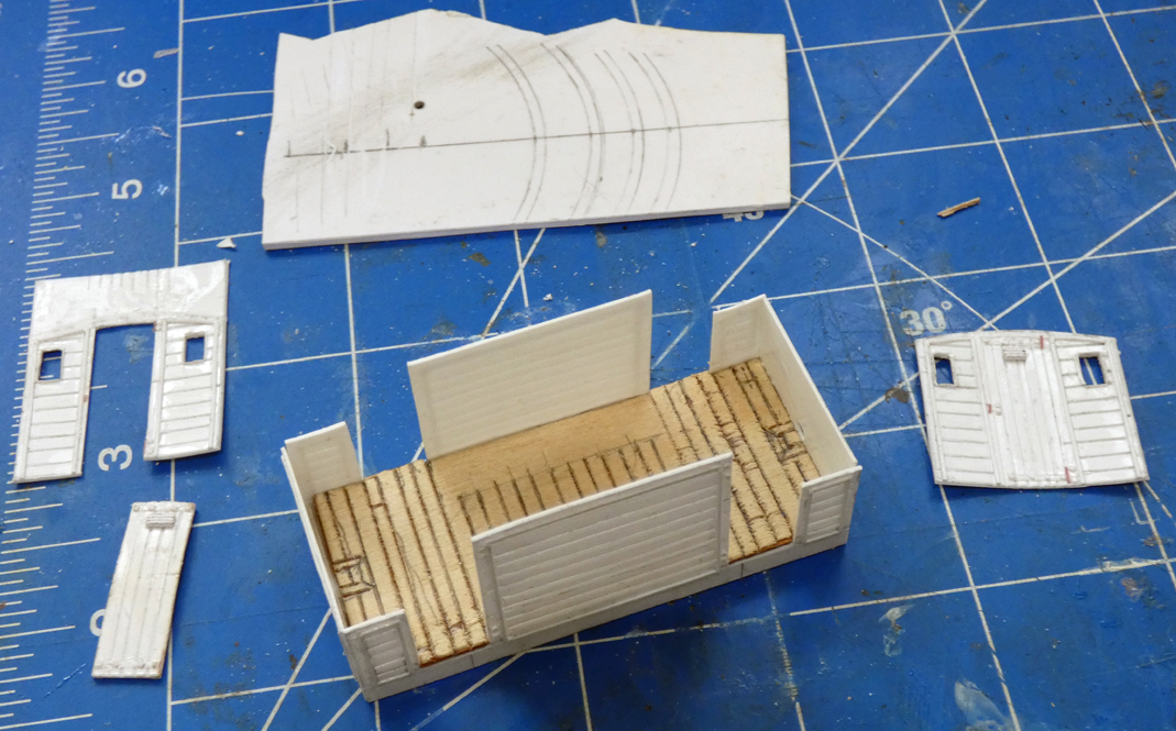 At this stage the floor of plywood has been fitted to the sides, ends and solebars; the cabin ends have been largely cut out and the roof supports marked out. It is very clear that that reinforcement of the body will be needed, as expected, to avoid distortion. One door will be modelled open, hopefully to let one see the inside of the van, but I've no idea on what colour(s) it should be painted. The sides will be vulnerable for a while as the cabin ends would clearly impede access to the verandas to enable the detailing of the insides of the ends to be done. So next step will be fitting the bracing of the ends but before all of that can be done the guard rails have to be fabricated and fitted, the support ring being fixed between the side and end pillar rather than attempting to drill the end pillar later (a near impossibility!).
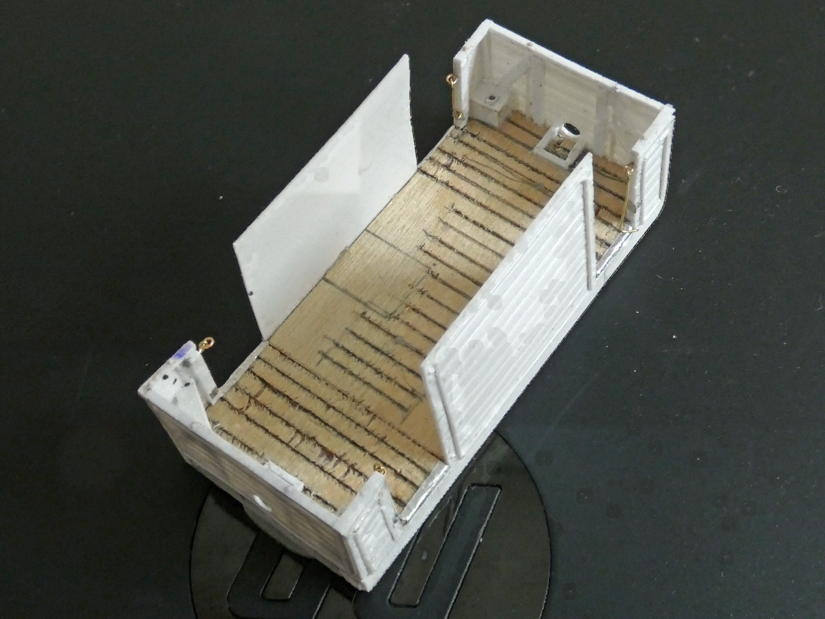
After a considerable break while the garage was being worked on, it's time to make more progress. The insides of the ends have been detailed with plastic strip including body framing, tie rods, brake column box, seat, battens to hold the tail lamps and kick plates at the entrances. I chickened out from making proper tie rods for the framing as I thought drilling through the diagonals and seats would be too difficult: I resorted to sticking in bits of slightly overscale (0.5 rather than 0.3mm) plastic rod. Painting the battens for the tail lamp, without painting the floor is going to be a challenge!
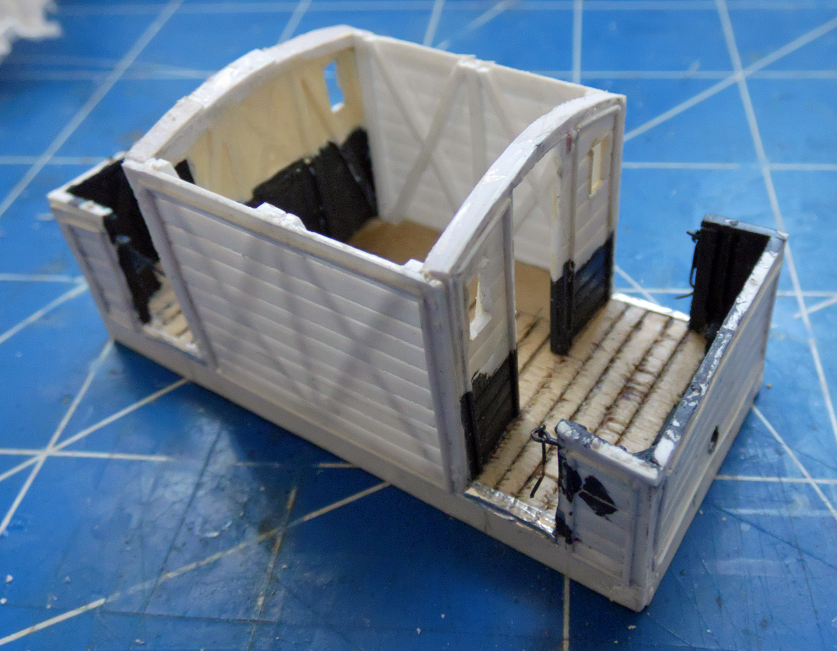
And so on to the next step: after having painted the insides of the verandas, the ends of the cabin have been fixed in place and the side framing added from 1mm square plastic strip. The ends were partially painted before assembly, as will be the inside boarding made from 10thou sheet.
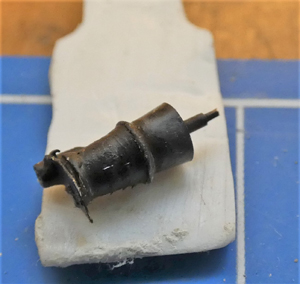
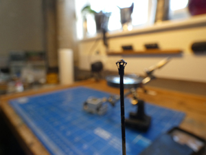
Some of the fiddly bits are the stove (turned brass plus extras) and the chimney cap - don't look too closely at this!
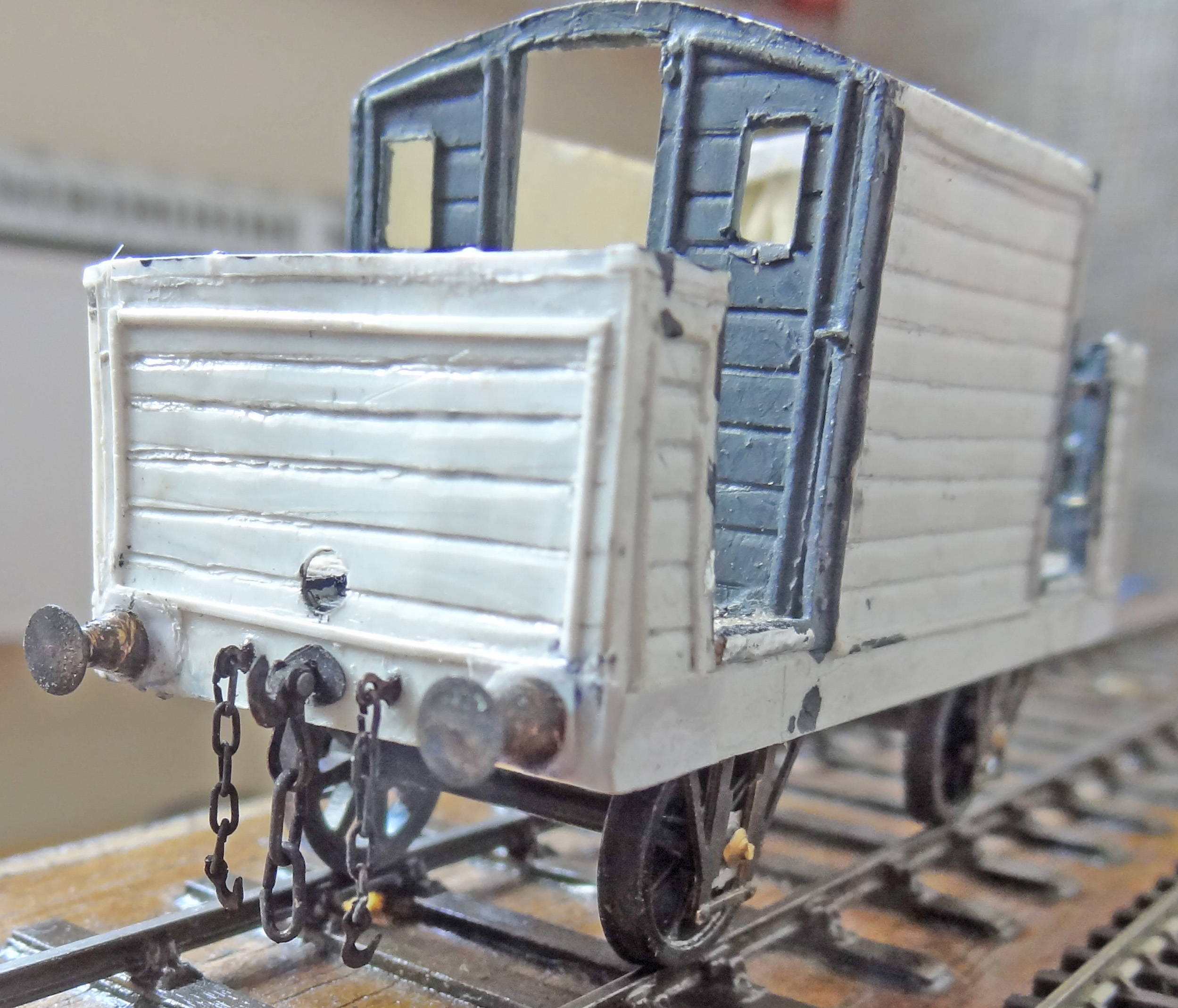 After a long break doing other things, work has started up again. During the break I managed, perhaps fortuitously, to loose the chimney cap so I'll have to make another one. The next steps were the installation of the internal benches/lockers, the stove and W irons (Masokits sprung variety). Then came the couplings: the main one has the top link fashioned from a screw coupling etch secured with an entomological pin. It should be round rather than flat but this is a compromise that I've decided to accept. Does anyone have a better way of making such links? The safety chains were a really tedious job as the only chain I had that was of the appropriate size was blackened from Ambis and this proved to be brittle. It must have taken at least half a dozen attempts at opening and closing each of the links to go through the eye on the buffer beam and the hook at the end of the chain. The work also served to prove that both my eyesight and dexterity are not what they used to be! (The eyes and hooks came from the same screw coupling etch: the carpet god claimed a few.)
Further progress has included the tie rods between the axelguards and the addition of axelboxes and springs (MJT Midland 8A). This should be followed by detailing of the solebars.
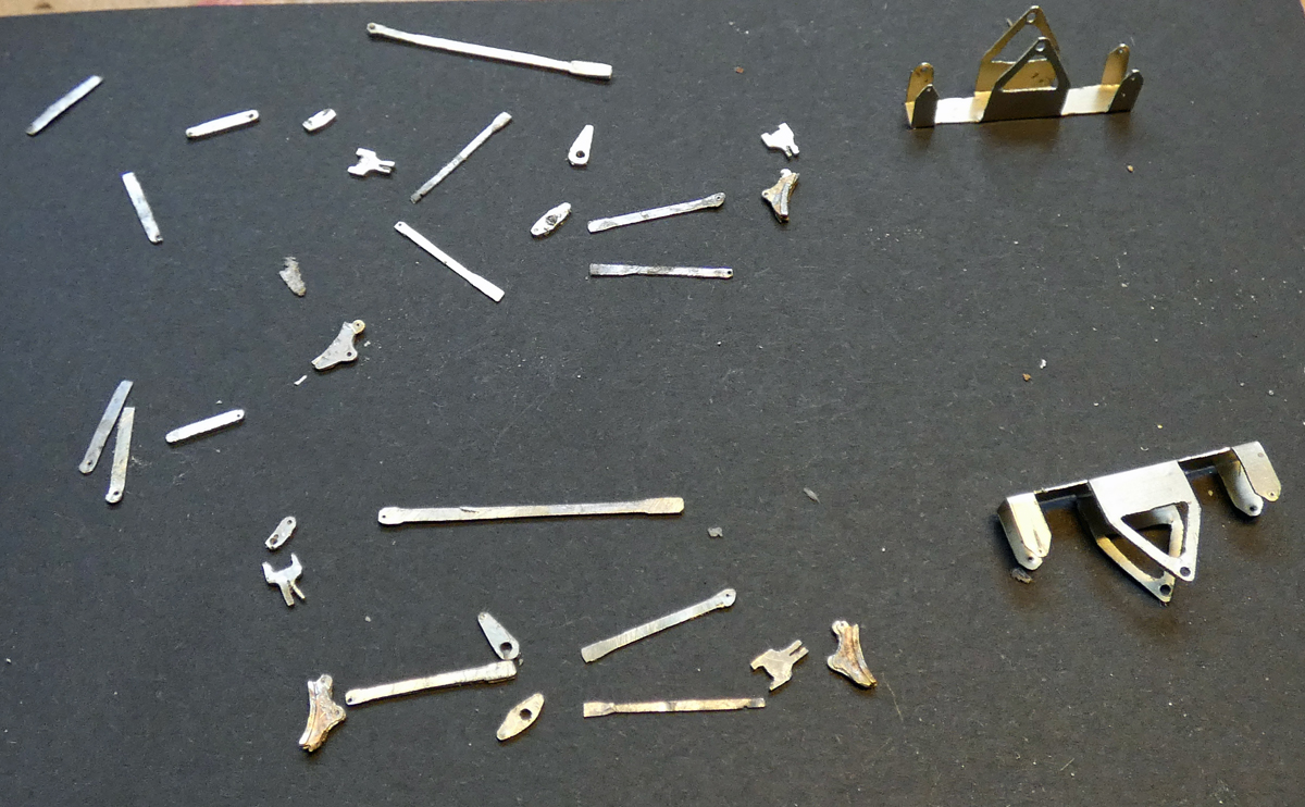
After another substantial break for prevarication I decided there was nothing for it but to start on the brake gear. Unfortunately no commercial product was close to the original design, even the V hangers were of non-standard width. So it was down to drawing, marking out and cutting lots of little bits mostly cut from two sheets of nickel silver soldered together to facilitate cutting out pairs of items. There were two notable failures on my part - I didn't even try to put holes in the push rods for length adjustments and I settled on a 2D rather than 3D representation of the brake hangers - I guess the prototype used castings for these. I also put the supports for the brake hangers 0.5mm closer to the centre line than they should be so as to give clearance between the brake blocks and wheels: I hope I estimated this correctly. So now it will be trying to solder everything together: will there be room to get a soldering iron in everywhere it is needed?

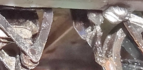 Well, there wasn't room for a soldering iron! So much of the brake gear was assemled with glue, but the fiddly little hangers were soldered to the brake blocks before assembly. Ideally the various bits would have been pinned together but this would have meant going for etching very small holes in the ends of the rods and being 100% certain in advance which holes to use to ensure everything fitted without brakes binding. During assembly it also became clear that the W-iron etches would foul part of the operating system (the support for the cranks below the brake standards to which the long operating lever is attached. The long operating lever that fits between the wheels and the W-irons may rub against the sprung bearing hangers - time will tell.
Must press on and try to finish this now that Jonathan David has published his lovely drawing in The Welsh Railways Archive (Volume VI No. 9 page 214).
Lessons have been learnt for when I try to model a similar TVR van: it will probably need etched brake gear plus specially designed W-irons and bearing supports to ensure there is no fouling. This may be a real design challenge! And I thought the most difficult bit would be the screw thread of the brake standard that is visible being outside the body.
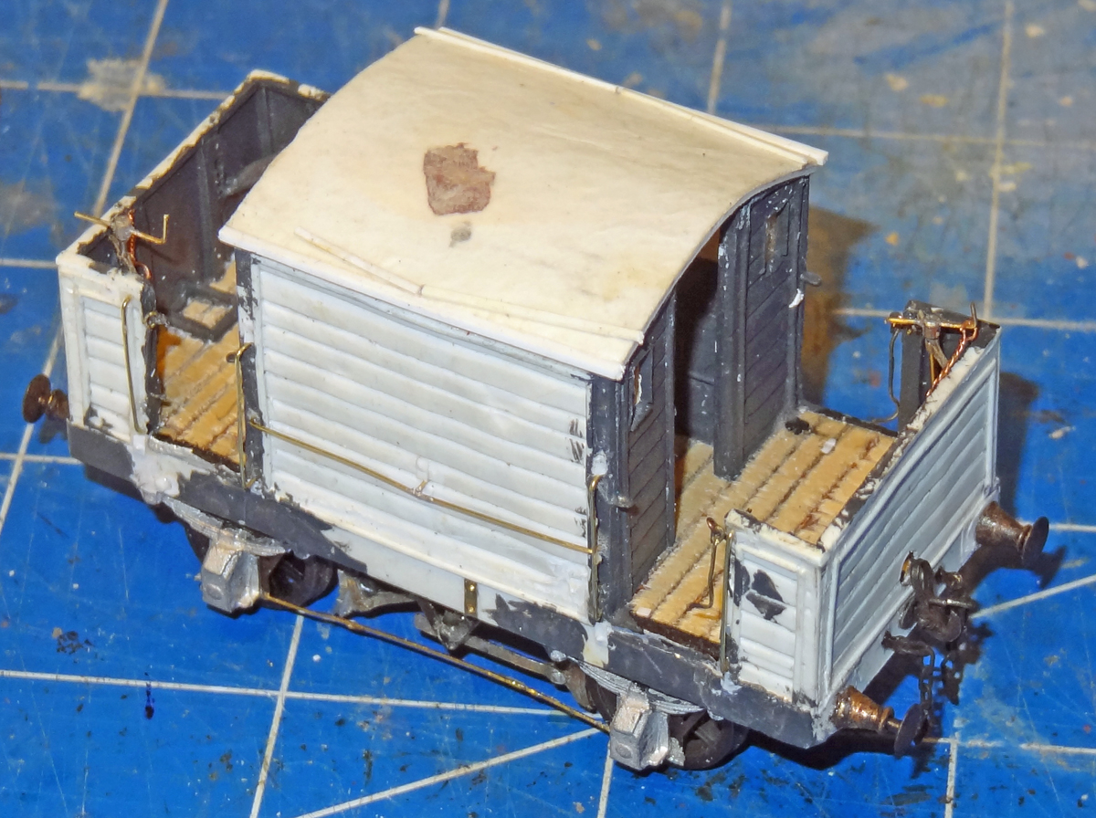 Time to get modelling again and to review some of the plans I had. First casualty was the idea of having a removable roof to be able to see the inside: I decided this would be a bit too much of a challenge so in went the roof supports, more or less according to the drawing and on went the roof from scribed 20thou plastic. The roof was then covered with a piece of tissue paper to give a little texture, edging strips added from 30thou strip (slightly overscale, they should have been 0.5*0.67mm) and rain strips from 0.5mm square plastic. Washer plates were fitted to the solebars and detailed using Archers Transfers: I'm not convinced that they will show up adequately when painted. Handrails were fashioned from 0.3mm wire, a pretty good approximation for the prototype's 7/8" with fixings simulated by 5thou plastic strip embosed to show bolt heads.
The next fiddly job was the brake columns from 0.5mm brass rod topped with a tiny bit of tube and a 0.3mm wire handle. The stabilizing brackets were made from two bits of 0.2*0.9mm nickel-silver and the securing chain from fine twisted copper wire.
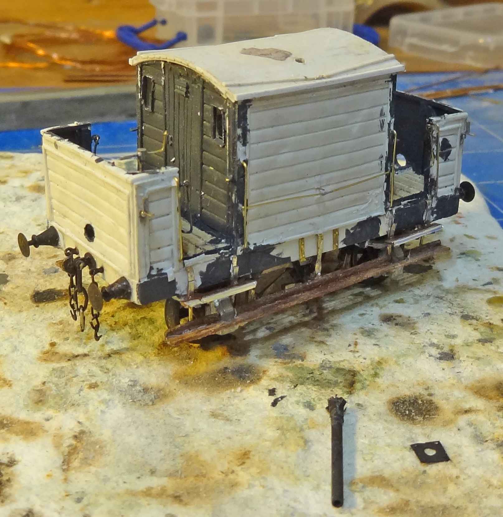 Progress now has been with the bits that are likely to get damaged... The first task was to work out how to make the footboard supports - I think these would ideally be lost wax castings as their shape is rather complex. I settled for hammering the end of a piece of wire flat bending over the end to support the lower footboard then glueing tiny brackets from 0.2*0.7mm strip to support the upper footboard - the support then being fixed to the solebar with super glue. Normally I would have preferred to pin the supports to the solebars but I've run out of suitable entomological pins and it appears that these are no longer made. The footboards are strip wood, the lower ones having a kick board and the upper ones having a metal angle edging made from aluminium foil.
The lamp irons were from the Masokits range being designated as smokebox door irons - these are not quite the right shape, the prototype being curved in parts and have been fixed with somewhat oversize pins using just one per iron rather than the two that would look better. I wonder how well these fragile fittings will stand up to having lamps put on and off.
The last detailing job was to make a chimney to replace the one I lost. The cap this time is more symetrical but it does stand somewhat too high above the pipe. The protection plate to go round it is from 2thou brass and blackened, as was the chimney. As the original idea was to have a removeable roof, the chimney is not fixed to the stove - location is by a little bit of wire in the end of the chimney that pegs into the vent of the stove.
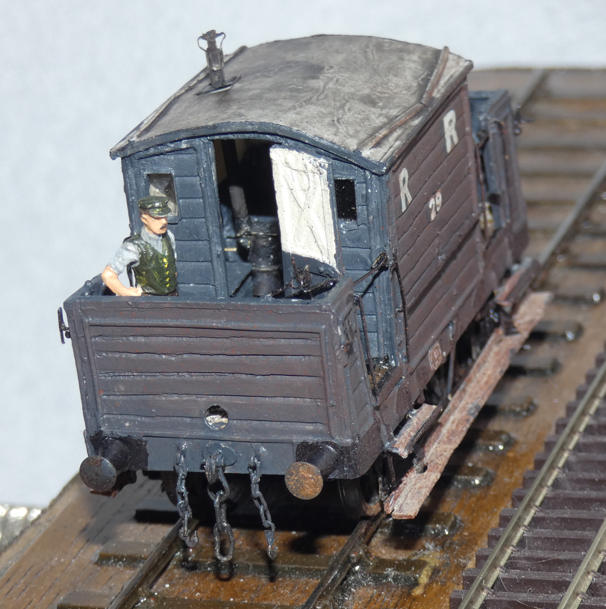
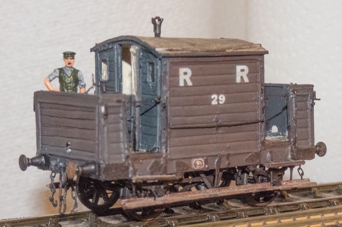 Finished! It was completed in all-over grey because the photos I have seen show no contrasting end colour and I wasn't happy with the idea of red for my planned layout period. Lettering was from old sheets in my store box and weathering done with the lettering cleaned up a bit - not quite as effective as I would have liked. No lamps added yet - does anyone know what the RR lamps looked like? None of the photos I have show any. The guard was just there for the photo - I've no idea what colour his uniform would have been.
Well, the whole exercise took much longer than I expected and I've certainly learned things along the way to help if I ever make anything similar in future. I was pleased with the chimney cap, couplings and the inside. Things that need to be done better include the brake gear, the hangers are a real challenge, and the footboard supports. I fear the sides may distort with time to show the internal cross bracing framework. All I have to do now is build a RR loco to go with the three brake vans that I have!
Those interested in the RR are also recommended to view Richard Spratt's web site, showing his impressive Penrhos Junctions project and much more of interest, particularly on RR goods vans.


 AJN's RR Page